Pages

Sunday, April 26, 2020

After effects Interface and Introduction pdf

After Effects Interface

Hey guys today we will discuss about Interface of After effects  and get introduce with this software. As we know After Effects is Motion graphics software which is used by many graphics editor for their professional works so let us now discuss  the interface of this software. 

But before starting our discussion on  After Effects Software, i think we should know each and every point about After Effects software because after going through major content of After Effects, handling of this software throughout our article became easy task for us. So let me tell you the major points of our article, so that you can get brief knowledge about this article.

These are major points which we will discuss in this article:

  • What is After Effects?
  • System requirement of After Effects software
  • File Format supported by After Effects
  • Interface of After Effects

So these are four major points of our discussion in this article. Let us now discuss them one by one.

What is After Effects software?


After Effects is mainly used for video editing work by video editing professional but it has wide range of working area some of them are we can make Motion graphics in it, we can animate object or any logos in this software, we can manipulate any video footage as well in this software. You can use this software as additional software with some other graphics designing software as per your requirement.

System Requirement of After Effects Software:


After Effects software was developed by Adobe Inc. in January 1993 as video editing software and today it is a part of Creative Cloud desktop application of Adobe systems. This software is compatible with Windows 10, Mac OS and their later versions. If you want this software on your laptop or on personal computer or on tablet you need these system requirements which are as follows:


For Windows
  • Processor required: Multi-core Intel Processor (64 bit)
  • Operating system required: Microsoft Windows 10 (64 bit) and its later versions
  • RAM required: 16 GB minimum required (32 GB recommended)
  • Hard disk Space required: 5 GB required (Additional free space required during installation of  software)
  • Monitor resolution required: 1280 X 1080 or greater
For Mac OS
  • Processor required: Multi-core Intel Processor (64 bit)
  • Operating system required: mac OS 10.13 and its later versions
  • RAM required: 16 GB minimum required (32 GB recommended)
  • Hard disk Space required: 6 GB required (Additional free space required during installation of  software)
  • Monitor resolution required: 1440 X 900 or greater

Internet connection required for both for different purposes such as for activation key, for updating the software and many others.

Now after getting knowledge about systems requirement of After Effects software another question come into your mind. ‘What is that? Let me tell you it is ‘which type of files supports in this software. So let us have a look on supported file of this software.

Which type of file format supported by After Effects?


We have number of file format that are supported by After Effects but i will tell you some important file format here in this article for your knowledge. These file format are as follows:

Audio File Formats

MPEG (Moving Picture Expert Group) formats such as MPEG, MPG, MPE, MPA,M2V, MP2, M2A, M4A, M2T, M2P, MPV, VOB, MOD, AC3, MP4, M4A, M4A.
AIF/AIFF (Audio Interchange File Format): it can be import and export both.
WAV (Waveform) it can also be import and export both.

Image File Formats:
  • Al, PS, EPS (adobe illustrator): these can import only in this software.
  • PDF (Portable Document Format): It can import only.
  • PSD (adobe Photoshop): it can both import and export in this software.
  • BMP, DIB, RLE (Bitmap): It can import only in this software.
  • JPEG/JPG (Joint Photographic Expert Group): It can both import and export in this software.
  • PNG (Portable Network Graphics): It can import and export both in this software.
  • TIFF/TIF (Tagged Image File Format): It can both import and export in this software.

These are some file format that supported in this software on Audio file format and Image file format basis.

 After Effects Interface


In the interface of After Effects we have number of sections which make its working easy for its user and provides a user friendly user interface. Today we will discuss all important sections of this software so that we can understand its working criteria. So guys let us start our article for getting knowledge about base of this software.


The user screen of after effects divided into few main sections. Let us start from the top of this software. At the top you will first find a Menu bar which contains different menus for performing different task in this software such as File menu, Edit menu, Composition menu and some other important menus.


Moving to next bar which is below to this menu bar this is Tool panel. It offers us some tools for performing graphics work in this software


Once you select any tool and use it for particular task, the properties of that tool can be seen at the right side of this tool bar.

For example let i take rectangle tool and draw a rectangle. 


Now you can see there is number of properties shown in property bat which is at the right side of tool bar such as Fill of this rectangle, Strokes of this rectangle and some other properties are there in property bar of this rectangle shape.


Now when you come to the middle of this software. You will find three main sections here. The left side section is Project Panel, the center section is known as Composition window and the right one is sections of some important tabs. Let us have brief knowledge about these three sections.


Project Panel : This section contains all your imported file in it, it also show you composition made by you in your work.


Composition window: Every thing you made in this software is know as composition. You will see all your work in this window actually it work as display window for you.


Tabs section : In this section we have different type of tabs for making our work easy during use of this software. Some of tabs are Effects & Presets tab, Align tab, Preview tab and some other important tabs are there.


Now let us move to bottom section of this software. At the bottom of this software we have two important section of this software such as Layer section and Time line section. Let us have brief knowledge of these two sections.


Layer Section : In this section we have all layer which are include in our composition.


Time line Section : In this section we make adjustment of our animation.


These are some important section of our User Interface of this software which will help us in learning of this software.

For next part of learning about after effects go to this blog.

https://gtxmentor.blogspot.com/2020/04/composition-setting-after-effect.html

Saturday, April 25, 2020

Auto cad loft command 2020

Auto cad Loft command


As we know guys Auto Cad is computer aided designing software which is most popular among engineering designing professionals. Auto Cad offers us many type of command for handling parameters of drawing in it. It has range of both 2d and 3d commands so today we will discuss one of 3d command of this software which is Loft command in auto cad.

What is Loft in Auto Cad?

Loft is one of the 3d modeling command through which we can covert a 2d shape into solid along a cross section or any particular path. So let us have a look on Loft command of Auto Cad.


How to use Loft in Auto Cad?


We can use loft on any 2d shape for converting it into a solid shape by following some options of this command such as along with path, along with cross section and some other. We will discuss these options one by one and also analyze parameters of loft command of its settings box.

Before going through this method let us have a quickly review on the User Interface of this software so that handling of this software become easy for us. Starting from top here we have different Menus such as Home menu, Insert Menu, Annotation menu and some others, each of them helps us for managing of command and tool of this software, move to next section that is display window which is at the middle of this software, in this window you can see your drawn object of any drawing or whatever you draw in this software that will be display on it, if we talk about button end of this software then there are many option of navigation which helps us in handling of parameters during our working in this software.

This is Drafting and Annotation workspace screen of this software which is set as by default screen of this software.


Now for loft command we have to switch the workspace to modeling workspace. For changing the work space go to Workspace switcher option which is at the lower right corner of this software and click on it. A popup list will be open, choose 3D Basic option from the popup list.


Now let us have polygon command. For this go to Draw tab of Home menu of this software and click on icon of polygon command. Now give the number of sides of polygon. I will enter 6 as a sides value of polygon

Now let us make a copy of this polygon. For making copy of this polygon go to Modify tab of Home menu of this software and click on the icon of copy command.

Now select this polygon by clicking on it and press enter key then specify the base point and drag the polygon for copying it.

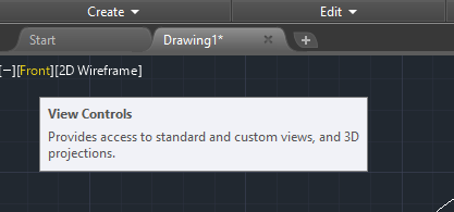
Now let us change the view of our drawing. For changing the view go to this View controls option of display window and click on it.


A popup list will be open choose Front view option from list.


Now i will take a Arc command from the Modify tab of Home menu of this software and make a arc like this.


Now again go to View control option and click on SE Isometric view option from the list.

Now go to Create tab of Home menu and click on the icon of Loft command. 


Now select both of the polygon with loft command one by one then press enter key.


Now command will ask you to select option for making solid shape with this loft command. I will choose Path option and press enter key. Now command will ask you to choose the path along which you want to make solid shape.

Once you choose the path loft will change it in this shape.

You can rotate it for seeing properly.

Now let us come to Top view again by View control.


Now again i will make two polygons like shown in figure. Then make a circle inside these polygons.


Now take move command from the Modify tab of Home menu and move shapes like shown in figure.

 Move shapes with same reference line for applying loft command properly.


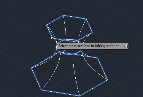
Now again take loft command and select shape one by one starting from bottom shape and loft command covert it into solid shape. This is wire frame view of this solid.


Now press enter key, then command will ask you to select options through which you want to make solid. Here choose Cross section option only from list. 


Now change it into shaded style view to see the shaded view and command will change this shape into solid as shown in figure.


Now let us again make a shape like this for learning about next option of loft command.

Now again take loft command and select the shape one by one and press enter key.

Now again command will give you options through which you want to use loft. Now select Guide option then press enter key.

Now command will ask you to select the guide lines so select these lines one by one.

Then press enter key and your shape will convert into solid shape as shown in figure.

Now again use loft command for making solid like this and click on Settings option of the list.


Once you click on settings option, a setting popup box will be open.

Here you can change the value of parameters of this command for changing the shape of solid as shown in figure.


So this is all about the loft command in Auto Cad. You can now handle its parameters without any problem and use it for making good object of engineering drawing. After this article there will be no doubt in your mind about loft command of Auto Cad.

Thursday, April 23, 2020

Auto Cad 3d Rotate


Auto Cad 3d Rotate


As we know guys Auto Cad is computer aided designing software which is most popular among engineering designing professionals. Auto Cad offers us many type of command for handling parameters of drawing in it. It has range of both 2d and 3d commands so today we will discuss one of 3d command of this software which is 3d rotate command in auto cad.

What is 3d rotate in Auto Cad?

3d rotate is a 3d modeling command by which you can rotate a 3d object in all of the three axis such as x, y and z axis by following its simple steps. We can use 2d rotate command also as 3d rotate command in some cases. So let us have a look on 3d rotate command of Auto Cad.


How to do chamfer in Auto Cad?


We can use 3d rotate command on any 3d object very easily, we just have to follow some simple steps. So for rotating 3d object in Auto Cad we have two methods that are by using by using 2d rotate command on 3d object and by using 3d rotate command of 3d modeling workspace. So first we will discuss 2d rotate in auto cad for rotating of 3d object.

Before going through this method let us have a quickly review on the User Interface of this software so that handling of this software become easy for us. Starting from top here we have different Menus such as Home menu, Insert Menu, Annotation menu and some others, each of them helps us for managing of command and tool of this software, move to next section that is display window which is at the middle of this software, in this window you can see your drawn object of any drawing or whatever you draw in this software that will be display on it, if we talk about button end of this software then there are many option of navigation which helps us in handling of parameters during our working in this software.

Auto Cad by default offers you a workspace window of 'Drafting and Annotation' workspace. This is Drafting and Annotation workspace for 2d drawing work.


Now for using rotate command on 3d object we have to switch to 3d workspace so go to Workspace switcher option which is a the bottom of the display window of this software. Click on it, a popup window will be open like this, choose 3d Basics workspace from here.
Once you click on this option your workspace will be change into this working window.


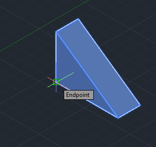
Now go to Create tab of Home menu and click on down arrow button of Box command icon. A popup list of command will be open, choose any one of the 3d object command. I will choose Wedge command for drawing a 3d object.


Now draw the base of Wedge by dragging mouse pointer or you can give a particular value to the base of this Wedge shape.


Now for giving height of this wedge you can give the value of height or simple drag the mouse pointer in the upward direction and press mouse click to draw it.


 Now go to Modify tab of Home menu and click on the down arrow key of Move command and click on Rotate command of popup list.


Now rotate command will ask you to select the object for rotation. I will select this 3d object with this command and press enter key.


Now the command will ask you to choose the point round which the object will be rotate so i will choose bottom point of this 3d object.


Now mouse the pointer to rotate it around your chosen point and press mouse click to rotate or you can enter a rotation angle through keyboard enter the press enter key for apply the value.


Now let us have a look on the second method for rotating any 3d object. For this method we have to again switch the workspace so again go to Workspace switcher and click on it. Choose 3D modeling workspace from the popup list and your workspace will look like this working window.

 Now go to Modify tab of Home menu and click on the icon of 3d Rotate tool for having it.


Now command will ask you to select the object for rotation. I will click on this 3d object.


And press enter key. Once you press enter key rotation angle of all axis will come on the center of this 3d object.


You can rotate this object in along any axis by selecting the rotation circle of that axis.

Select that circle around which you want to rotate by click on it with mouse button and move mouse pointer for rotation.


You can give angle of rotation manually through keyboard enter then press enter key. I will give 60 degree of rotation angle then press enter key for rotation.


So this is all about the 3d rotate command in Auto Cad. You can now handle its parameters without any problem and use it for making good object of engineering drawing. After this article there will be no doubt in your mind about 3d rotate command of Auto Cad.


After effects timeline

After effects timeline What is timeline in after effects Timeline is an important section of after efftect from where we make adju...